1

For some reason, existing 2D analysis softwares for sport do not seem to have provisions to correct or take into account lens distortion¹.
This is unfortunate because the 2D measurements assume that all points are coplanar, and lens distortion is bending that plane.

Stating the obvious:
http://www.kinovea.org/screencaps/0.8.x/lensdistortion/distorted-measures.png
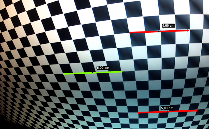
Fig 1. Ridiculous measurements on a checkerboard pattern displayed on a flat LCD screen, filmed with a 170° lens (GoPro Hero 2 at 1080p).


The green line was used for calibration and has a length of 5 squares. The red lines have the same pixel length as the green line so without any other form of correction they also display the same physical length, which is obviously wrong.
The wide angle lens primarily exposes radial distortion, no amount of plane alignment or perspective plane calibration is going to fix this.

The current suggested approach is to first undistort the video in an external software and then use the undistorted video for your 2D analysis.

The problems with this approach are that:

  • You need to do it for every input video,

  • It may degrade the quality of the footage as it implies a re-encoding,

  • The software used may be more oriented towards "pleasing to the eye" results rather than mathematical rigor and may use a simplified distortion model.

It's not just fisheye lenses. Almost all cameras have some form of distortion even though it's not always readily noticeable.


Here is the plan to integrate lens distortion into Kinovea.

  1. A new drawing tool "distortion grid" allowing the user to place a grid on top of a checkerboard like pattern.

  2. A module to compute lens distortion parameters based on the distortion grids you added throughout the video.

  3. A module to save and load distortion parameters as "profiles", for reuse with all videos from that specific camera.

  4. Usage of the distortion parameters to compute undistorted coordinates and usage of these coordinates to make all measurements in Kinovea.

  5. Usage of the distortion parameters to redistort straight lines into curves for displaying purposes. Interesting for lines, angles, rectangular grids, perspective plane and coordinate systems.

  6. [Nice-to-have] Import of calibration files from third party photogrammetry software.

Note that it is not planed to undistort the images themselves in real time. Rather, I would like to keep the video untouched, but use the distortion parameters for measurements and display.

I will use this topic to post updates on the progress of this feature. It may take a while since there are plenty of other topics that are in progress, completion of the 0.8.22, bug fixing, etc. Your feedback is nonetheless highly appreciated.

----
¹: The popular commercial packages for 2D analysis (Dartfish, Quintic) do not seem to have any lens distortion related features. If you know otherwise, please post a comment.
The Centre for Sports Engineering Research at Sheffield Hallam University (UK) has developed a software called Check2D, it is the first effort to my knowledge to address the issue in the context of sport study. Background and case study (PDF).
Softwares rebuilding 3D coordinates from multiple cameras are immune to lens distortion.

2

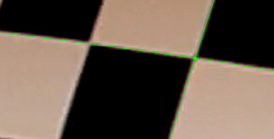
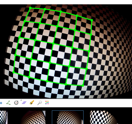
1. A new drawing tool "distortion grid" allowing the user to place a grid on top of a checkerboard like pattern.
(The easy part).

http://www.kinovea.org/screencaps/0.8.x/lensdistortion/drawingdistort2.png
(I have enlarged the width of the grid lines for the screenshot.)

At 6x zoom:
http://www.kinovea.org/screencaps/0.8.x/lensdistortion/drawingdistort-zoom.png

Manually placing the grid points might prove cumbersome. Many calibration tools have a function to automatically find corners in the image, we'll see.

3

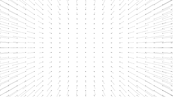
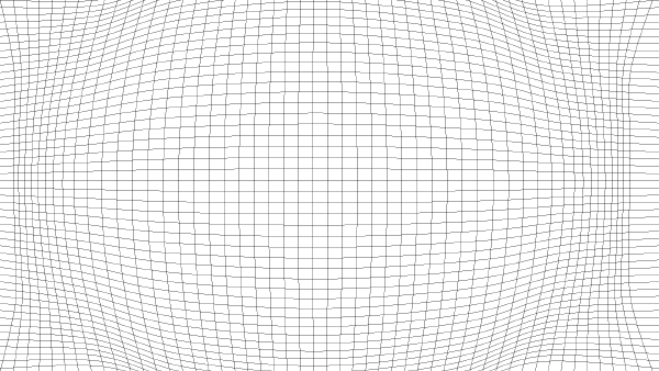
"2. A module to compute lens distortion parameters based on the distortion grids you added throughout the video."

Distortion map computed using data from the grids added the video of the previous snapshot.

As a vector field:
http://www.kinovea.org/screencaps/0.8.x/lensdistortion/vectorfield-small.png

As a distortion grid:
http://www.kinovea.org/screencaps/0.8.x/lensdistortion/distortiongrid-small.png

GoPro Hero 2 at 1920×1080@30fps (170°). Calibration used 5 sets of 25 points fed to OpenCV's cvCalibrateCamera2 to compute the distortion coefficients and camera intrinsics parameters. The distortion grid is drawn using the direct equations to distort back the coordinates.

4

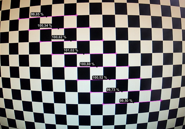
"4. Usage of the distortion parameters to compute undistorted coordinates and usage of these coordinates to make all measurements in Kinovea."

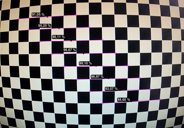
Some measurements done filming the checkerboard pattern "roughly" orthogonal to the camera axis. Pictured lines, spanning 5 squares, are ±1% from each other in measured length (still true close to the border of the image).
http://www.kinovea.org/screencaps/0.8.x/lensdistortion/calibrated.png

For comparison, the same lines without lens distortion calibration :
http://www.kinovea.org/screencaps/0.8.x/lensdistortion/uncalibrated.png
(Lines at the edges of the image go down to 50% of their ground truth.)

For this test lens distortion coefficients were computed in an external (free) application and imported automatically. The geometric calibration used a grid spanning 10 squares and marked as 200% in length.

5

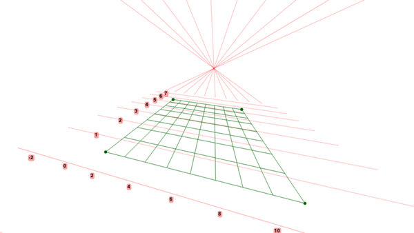
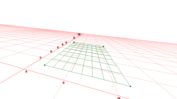
I am making a rather large detour through projective geometry, homogenous coordinates and line clipping algorithms to fix the rendering of the coordinate system related to the plane calibration. Since the plane and the origin are user-defined, there is plenty of room for awkward cases and unusual sizes or orientations.

http://www.kinovea.org/screencaps/0.8.x/lensdistortion/projective-plane-0.8.22b.png
Fig 1. 0.8.22, with an example of a completely broken rendering of the coordinate system: Visible vanishing point, lines behind the camera projected above the horizon, limited extension of the grid on the plane yielding mostly empty space.

http://www.kinovea.org/screencaps/0.8.x/lensdistortion/projective-plane-0.8.23b.png
Fig 2. 0.8.23, better rendering of the same coordinate system. (No 3D framework involved, pure projective geometry).

6

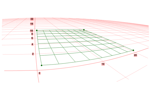
More progress, almost done:

http://www.kinovea.org/screencaps/0.8.x/lensdistortion/distortedcoordinatesystem-s.png
Fig1. Final coordinate system with perspective and distortion correction.


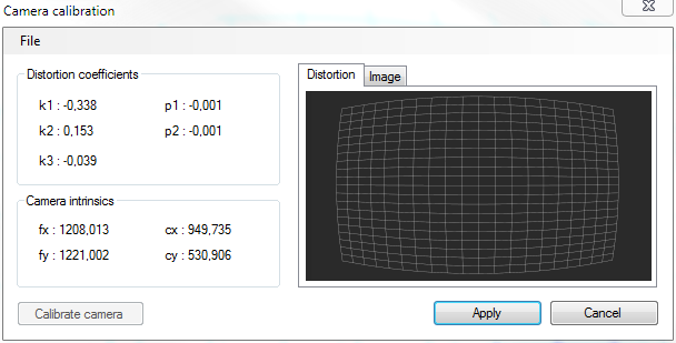
http://www.kinovea.org/screencaps/0.8.x/lensdistortion/cameracalibrationdialog.png
Fig 2. The camera calibration dialog. Here the coefficients correspond to a GoPro Hero 2 in Medium mode (127°).


Basically there are two ways to get the distortion coefficients. Both imply filming a checkerboard like pattern, then:

  • In Kinovea, by creating several "Distortion grids", positionning them manually and then clicking "Calibrate camera" in this dialog.

  • By using Agisoft Lens (freeware), importing the images and performing the (automated) calibration there. Then by importing the resulting XML file in Kinovea through this dialog.

This is a one-time-per-camera operation.

The "Image" tab shows a rectified version of the current image, however it is for ballpark verification, there is currently no plan to provide real time image rectification.

I'll describe in more details later how I verify that the lens distortion and perspective correction are correct.

7

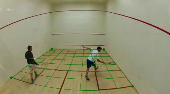
Distortion correction in action in a less rigorous setting.

http://www.kinovea.org/screencaps/0.8.x/lensdistortion/distortedsquash.jpg
Fig 1. Plane mapping on a video from a different camera and at different resolution than the camera used to compute the distortion coefficients.

Here for example I have downloaded a squash video off YouTube in a crappy resolution (426×240). The only thing I know about the video is that it was filmed with a GoPro at the "Wide" setting (170°).

I imported distortion coefficients from my own camera and added a grid tool (in green) simply placing its four corners at field marks. Even though the cameras used are not the same, the grid tool can still be used if the required accuracy is not down to the centimeter. For example coordinates of points on the grid could be used to create a heat map of foot positions (and see how "hot" is the T for a particular play).

For better accuracy the calibration should be done on the same camera. The assembly process introduces small differences from one camera to another.

8

joan,
first of all congratulations & big big THANK YOU! for this wonderful software.
I'd write more superlatives, but let's go back to the main subject:
1. I completed the lens distortion calibration for a PS3Eye, worked like a charm.
2. You wrote above that this is a "one-time-per-camera operation". So no additional savings as .kva are required? Imagine, I would like to analyse the records on another PCs - another calibration required, or can I export (somehow) to .xml & import to proceed? You wrote that you were importing the distortion coefficients - how, with the mentioned Agisoft software or using Kinovea? Maybe, the community members who have done it for their cams can upload those files & share them? I can do so for my cams (I know, the distortion of the PS3Eye is rather very low), once I've figured out how to export distortion coefficients.
Thanks a lot in advance & have a nice day!

- the repairman will never have seen a model quite like yours before -

9

Hi,

You can export the calibration parameters from within the calibration dialog using menu File > Save. The default directory is under "CameraCalibration" in the application data directory. Then from the second PC open a video, open the calibration dialog again and do File > Open and point it to the xml file.

To be clear, when you "Open" or "Save" it uses Kinovea format. When you "Import" it imports Agisoft Lens format. You can also directly reuse the Agisoft file and import it from the second PC.
You need to open/import it for each video.

The same file can be used for the same camera as long as the camera configuration doesn't change focal length, aspect ratio, etc.

For example on the PS3Eye there are two zoom positions by turning the ring.
On the GoPro depending on the configuration you can end up in Wide or Medium, 170° and 127° respectively I think. A different file is needed.

Technically each camera unit will have slightly different values. For example one of the computed parameters is the center of the lens relatively to the center of the sensor. It will not be exactly the same from one camera to the next.

That being said, the error introduced by these microscopic differences is probably less than the error of the calibration process itself, and less than the error introduced during coordinates digitization. So it may be fine to reuse a file created for a different camera unit unless you are already in an extremely controlled setting.

I'll gladly publish contributed calibration files on a dedicated page on the site so we can share them and experiment. Send them to joan at kinovea dot org and add details on the configuration with which they were created. If you validate that they also work at other configurations please mention it as well.

10 (edited by getpa 2016-01-25 13:41:29)

Thanks a lot,
will do so asap for PS3Eye (have 4 of them, so will do the unit calibration results comparison) and the Microsoft Cinema LifeCam.
Just a hint for those trying to record two or more PS3Eye cams simultaneously:
With Kinovea, there are workarounds how to get 2 cams working at the same time that can be found here in the forum. It works.
By chance, I came across a freeware soft called "iPi Recorder 2" that enables you to record 4 PS3Eye cams with 60Hz simultaneously.
To analyse with Kinovea, you can export/import the files & have some nice records perfectly synchronized. The whole thing might be worth a separate topic.
best regards

- the repairman will never have seen a model quite like yours before -