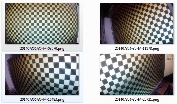
bluesrumba wrote:I saw that there is a new function "camera calibration". I thought that could be used to correct the wide angle of some cameras (like the action cameras) .
Here are some notes I wrote last year regarding lens calibration. They should still be relevant I think, let me know if it works.
Summary : film checkerboard pattern, import 5 images to Agisoft, export calibration file, import calibration in Kinovea.
1. In Agisoft Lens: Tools > Show chessboard.
2. Film the screen with the camera from up close. About 10 cm for a GoPro. Film from 5 different angles: one central and the others from the corners. This assumes a flat screen. See example images below.
3. Open the video in Kinovea.
4. In Kinovea: Find 5 clear images (no motion blur) corresponding to the 5 various points of view and export them as images.
5. In Agisoft Lens: Tools > add photos. Add the 5 images.
6. In Agisoft Lens: Tools > Calibration. Check every checkbox except "skew" and "k4". Run calibration.
7. In Agisoft Lens: File > Save calibration…
8. In Kinovea: Image > Camera calibration. File > Import > Agisoft Lens. Import the file and Apply.
Done.
You can reuse the same calibration file for all videos filmed with this camera with the same lens settings. (If you change from wide angle to normal, another calibration file is needed.) Other cameras of the same model will have similar calibration files, but for the most accurate result you'll want to use a file specific to your camera.
The calibration computes the focal length, the misalignment of the lens center with regards to the sensor center, optical axis orientation with regards to the sensor plane, and distortion coefficients.
Verification
1. Go into the image tab in the calibration window and check the rectified image.
2. With a perspective plane.
- Reopen the checkerboard video in Kinovea.
- Add a perspective grid on the checkerboard and verifies that the lines are correctly distorted.
- Zoom to the max, adjust corners of the perspective grid and then calibrate the grid by the number of blocks covered horizontally and vertically.
- Display the coordinate system and check that it is correctly distorted. You can see the error accumulating at the periphery.
- Add a line covering a number of blocks, display its measurement and check that it matches.
My calibration images looked like this:


