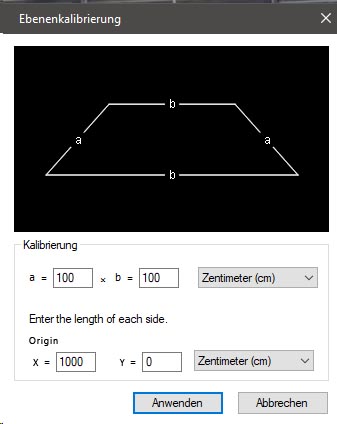
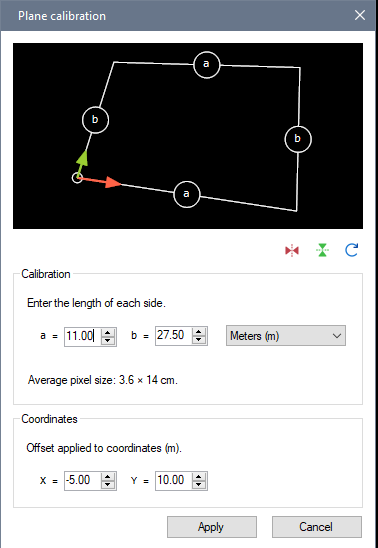
OK but it needs to interact nicely with changing the origin manually from dragging the Coordinate system object around by the axes or the origin. If we change manually on screen and we come back in this dialog it needs to show a correct value.
And we can also activate tracking on the coordinate system. In this case the value we would show here would be a bit tricky, maybe in this case it should be grayed out.
There are two ways to think about this I think. Option 1: this defines where the origin of the coordinate system is in relation to the calibration grid, this is what you wrote. When we activate the display of the coordinate system it will be moved to this new origin. If the origin is far enough it could be outside the image.
Option 2: it could define the coordinate at the origin, that is, a fixed offset applied to the coordinate system such that the intersection of the axes is not {0, 0} but something else.
This is sort of what I do in the new "Distance grid" object (on horizontal axis only though, but it could be done on two axes). In the calibration of this grid you set two distances, for example 6m and 10m, and then even a coordinate on the main axis is already at 6m. This was designed as an experiment for long jump measurements. The important advantage of doing it this way is when the true origin of your coordinate system is way outside the image. So we have a camera looking at the end of the long jump pit with markers at known distance. The coordinate system is still aligned with the grid but the values are pre-transformed. (edit: it doesn't really work fully with the coordinate system at the moment though, only for the distance line inside the grid).
Can you tell if your use case is more amenable to one way or the other? I wonder if people that want to change the origin numerically are actually looking for option 2.


